Domestic Roof Drainage Systems
An important consideration when designing a roof drainage system is to ensure that appropriate overflow measures are put in place in order to prevent water from flowing back into the building. This document has been developed to assist Queensland Sheet Metal customers with designing their roof drainage systems to ensure that they comply with the current Building Code of Australia (BCA).
With a wide range of roofing supplies, rainwater systems, downpipes and guttering supplies available, we can help you with all aspects of your overflow systems.
The National Construction Code 2016 (NCC2016) – New Overflow Requirements
The NCC2016 Volume 2 contains new overflow requirements for domestic eaves gutters. Performance requirements can be met by designing and installing gutters and downpipes for a Class 1 (eg. domestic residence) or Class 10 (eg. open carport) in accordance with acceptable construction practice described in section 3.5.2 of the NCC2016, or by designing in accordance with AS/NZS3500.3 or AS/NZS3500.5, or a Performance Solution as described in the NCC.
Gutter Overflow Options
There are two options when designing your overflow systems:
1. Continuous system – this operates over the entire length of the gutter (eg. slotted gutter and/or controlled back gap using spacers).
2. Dedicated system – this collects and removes the overflow in a given location (eg. using a rainwater head).
A roof drainage designer can meet the overflow volumes by using either or a combination of the two options.
Responsibilities of the Designer
It is the designer’s responsibility to design a rainwater system which allows adequate drainage to occur. The designer may be an architect, a builder, a hydraulic engineer, a home owner, or a roofing or guttering contractor.
The design and installation of a rainwater system needs to comply with the NCC2016 requirements or the Building Code of Australia and Australian Standards AS/NZS 3500.3 Plumbing and Drainage, Stormwater Drainage or AS/NZS 3500.5 Plumbing and Drainage, Housing Installations.
Responsibilities of the Installer
It is the installer’s responsibility to ensure the rainwater system is installed as per the requirements outlined by the rainwater system’s designer.
Adequate fall towards the downpipes must be given to gutters (a minimum of 1 in 500 for eaves gutters and 1 in 200 for internal gutters).
The installer must ensure that the correct number of downpipes of sufficent size are installed, that they are clear of debris and able to discharge correctly.
Maintenance
To ensure longevity of your rainwater system and trouble-free performance, it is essential that regular maintenance takes place. Gutters must be regularly cleaned to prevent the build up of debris, fungus or any other materials that could block the flow of water from the roof.
How Queensland Sheet Metal Can Help
Queensland Sheet Metal is an industry leading provider of metal roofing supplies and rainwater systems, including guttering and downpipes. Our experts are highly experienced in these systems and can assist with appropriate product selection, compliance requirements, and practical roofing solutions. Call Queensland Sheet Metal on 07 3267 1010 or contact us online for fast, friendly service and all the help you need.
Information extracted from the NCC2016 Volume 2 and is relevant for Queensland.
Table 1
| Rainfall Duration Intensities for Queensland | ||
| Locality | 5 minute duration rainfall intensity (mm/h) | |
| Average recurrence interval (ARI), once in | ||
| 20 years | 100 years | |
| Bamaga | 252 | 298 |
| Brisbane | 234 | 305 |
| Ipswich | 211 | 278 |
| Victoria Point | 245 | 320 |
| Bundaberg | 265 | 340 |
| Cairns | 229 | 278 |
| Cloncurry | 218 | 278 |
| Innisfail | 248 | 301 |
| Mackay | 250 | 316 |
| Mt Isa | 199 | 260 |
| Noosa Heads | 258 | 331 |
| Rockhampton | 229 | 300 |
| Toowoomba | 203 | 268 |
| Townsville | 235 | 300 |
| Weipa | 239 | 283 |
[/fusion_toggle]
Table 2
| Overflow Volume for Continuous Measure (L/s/m) | ||||||||
| Design 5 minute duration rainfall intensity (m/h) | Ridge to gutter length (m) | |||||||
| 2 | 4 | 6 | 8 | 10 | 12 | 14 | 16 | |
| 150 | 0.08 | 0.17 | 0.25 | 0.33 | 0.42 | 0.5 | 0.58 | 0.67 |
| 175 | 0.10 | 0.19 | 0.29 | 0.39 | 0.49 | 0.58 | 0.68 | 0.78 |
| 200 | 0.11 | 0.22 | 0.33 | 0.44 | 0.56 | 0.67 | 0.78 | 0.89 |
| 225 | 0.13 | 0.25 | 0.38 | 0.50 | 0.63 | 0.75 | 0.88 | 1.0 |
| 250 | 0.14 | 0.28 | 0.42 | 0.56 | 0.69 | 0.83 | 0.97 | 1.1 |
| 275 | 0.15 | 0.31 | 0.46 | 0.61 | 0.76 | 0.92 | 1.1 | 1.2 |
| 300 | 0.17 | 0.33 | 0.50 | 0.67 | 0.83 | 1.0 | 1.2 | 1.3 |
| 325 | 0.18 | 0.36 | 0.54 | 0.72 | 0.90 | 1.1 | 1.3 | 1.4 |
| 350 | 0.19 | 0.39 | 0.58 | 0.78 | 0.97 | 1.2 | 1.4 | 1.6 |
| 375 | 0.21 | 0.42 | 0.63 | 0.83 | 1.0 | 1.3 | 1.5 | 1.7 |
| 400 | 0.22 | 0.44 | 0.67 | 0.89 | 1.1 | 1.3 | 1.6 | 1.8 |
Table 3
| Overflow Volume for Dedicated Measure (L/s) | |||||
| Design 5 minute duration rainfall intensity (m/h) | Roof catchment area (m2) | ||||
| 30 | 40 | 50 | 60 | 70 | |
| 150 | 1.3 | 1.7 | 2.1 | 2.5 | 2.9 |
| 175 | 1.5 | 1.9 | 2.4 | 2.9 | 3.4 |
| 200 | 1.7 | 2.2 | 2.8 | 3.3 | 3.9 |
| 225 | 1.9 | 2.5 | 3.1 | 3.8 | 4.4 |
| 250 | 2.1 | 2.8 | 3.5 | 4.2 | 4.9 |
| 275 | 2.3 | 3.1 | 3.8 | 4.6 | 5.3 |
| 300 | 2.5 | 3.3 | 4.2 | 5.0 | 5.8 |
| 325 | 2.7 | 3.6 | 4.5 | 5.4 | 6.3 |
| 350 | 2.9 | 3.9 | 4.9 | 5.8 | 6.8 |
| 375 | 3.1 | 4.2 | 5.2 | 6.3 | 7.3 |
| 400 | 3.3 | 4.4 | 5.6 | 6.7 | 7.8 |
[/fusion_accordion]
Continuous Overflow Solutions
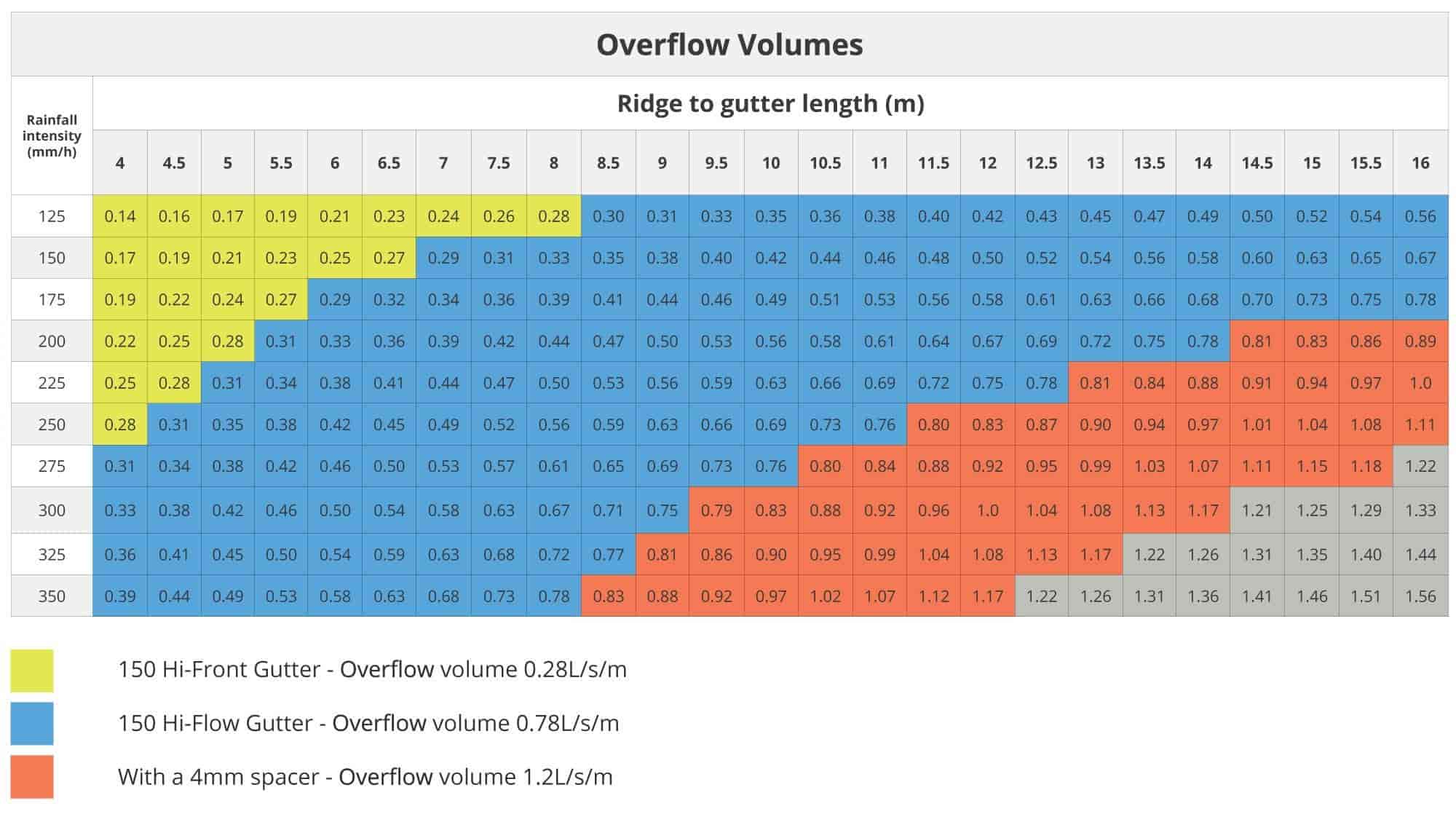
The following overflow solutions provide a measure for continuous overflow for the full length in which the solution is applied. These can be applied in combination with dedicated measures if further overflow capacity is required.
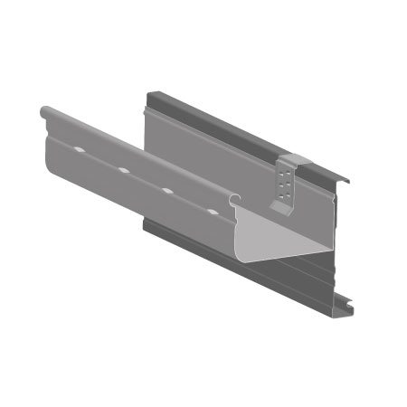
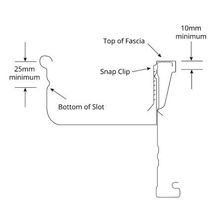
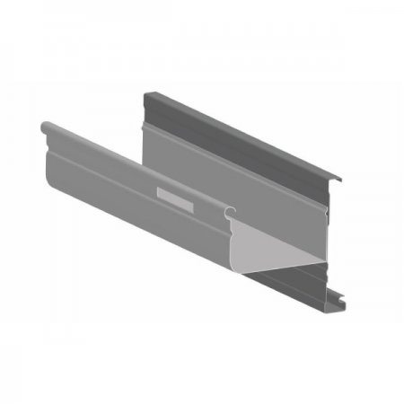
150 Hi-Front Gutter (Slotted)
The bottom of the slots in the front face of the gutter should be a minimum of 25mm below the top of the fascia. The top edge of the back of the gutter should be 10mm minimum below the top of the fascia.
Overflow Capacity = 0.28L/s per outlet
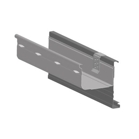
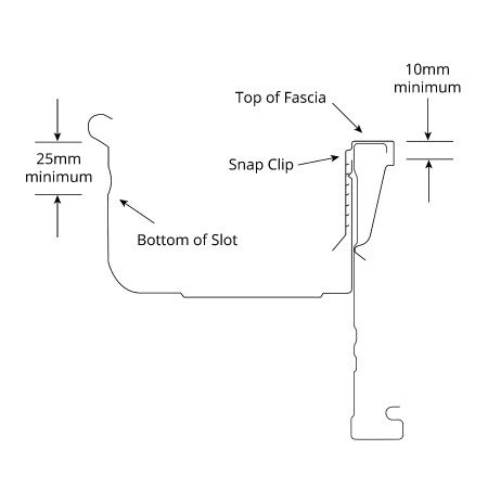
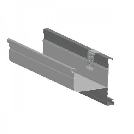
150 Hi-Flow Gutter (Slotted)
The bottom of the slots in the front face of the gutter should be a minimum of 25mm below the top of the fascia. The top edge of the back of the gutter should be 10mm minimum below the top of the fascia.
Overflow Capacity = 0.78L/s per outlet
Front Gutter Height
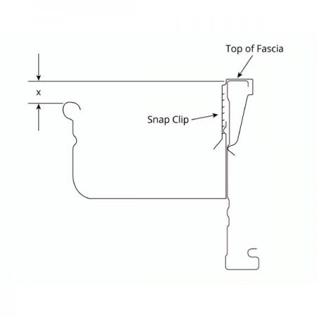
Water will overflow to the front of the gutter if the top of the front gutter bead is located below the top of the fascia. Due to the gutter fall, this may occur towards the end of a gutter run in, which case the portion of gutter beginning 5mm below the top of the fascia may be used in the overflow calculations.
| Dimension, X (mm) | Overflow Capacity (L/s/m) |
|---|---|
| 5 < x < 10 | 0.6 |
| 10 < x < 15 | 1.5 |
| 15 < x < 20 | 3.4 |
Back Exit Gap
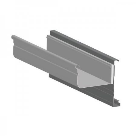
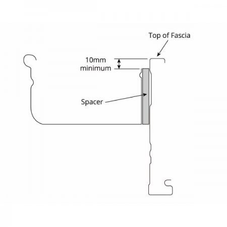
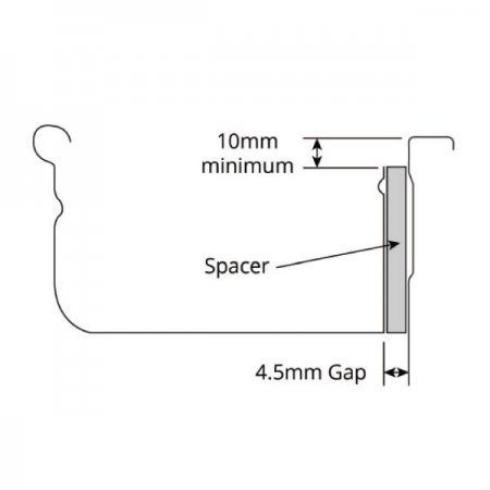
A spacer creates a consistent gap between the gutter and fascia and will allow water to escape through the gap without entering the building. Spacers are clipped to the back of the gutter at a maximum of 900mm centres. The back of the gutter shall be at least 10mm below the top of the fascia and the gap at least 1.5mm wide.
| Average Back Exit Gap (mm) | Overflow Capacity (L/s/m) |
|---|---|
| 1.5 | 1.20 |
| 3.0 | 1.40 |
| 4.5 | 1.50 |
| 6.0 | 1.55 |
Dedicated Overflow Solutions
The following overflow solutions will provide a dedicated overflow in litres per second for the individual measure. In some cases these measures can be located intermittently along the gutter to obtain the total overflow required or may be suitable as a stand-alone.
Internal Outlet
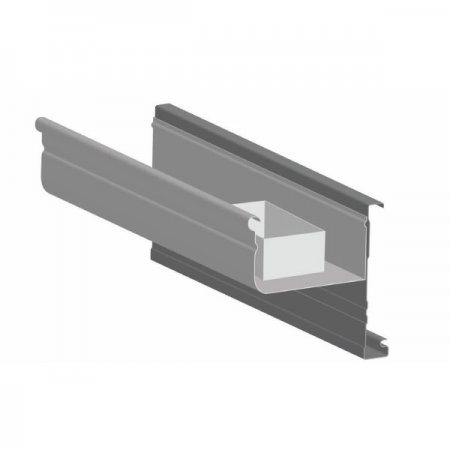
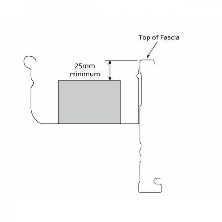
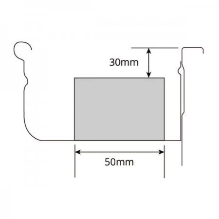
An internal outlet with minimum dimensions of 100mm x 50mm positioned lengthways in the gutter will overflow water internally from the gutter once it reaches a certain level. The top of the outlet shall be located at least 25mm below the top of the fascia.
Overflow Capacity = 1.2L/s per outlet
Cut-Down Stop End
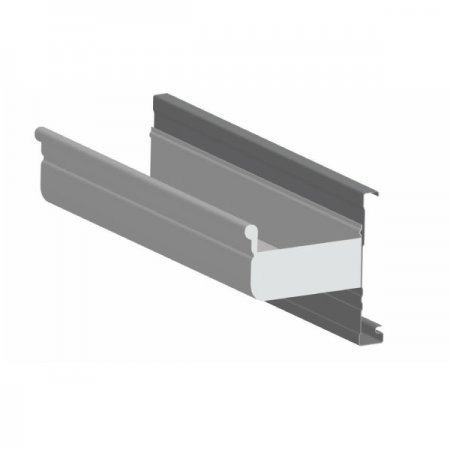
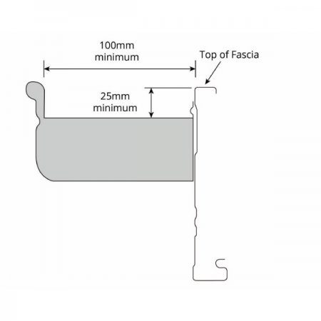
As long as it is not abutting a wall, a stop end which is cut down to create a weir will allow for some additional overflow. The cut-down shall be at least 100mm wide with the lower edge at least 25mm from the top of the fascia.
Overflow Capacity = 0.5L/s
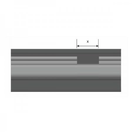
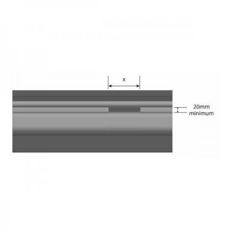
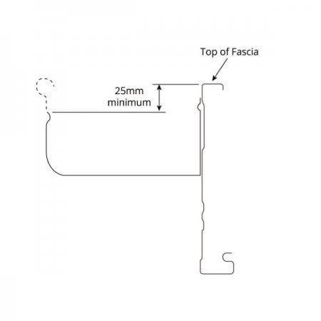
Front Face Cut-Down or Weir
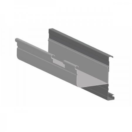
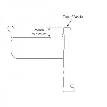
A manually cut slot or cut-down at appropriate intervals in the front face of the gutter will remove overflow from the front of gutters. The lowest edge of the cut-out shall be at least 25mm below the top of the fascia and shall be minimum of 20mm deep.
| Width, X (mm) |
Overflow Capacity (L/s) |
| 100 | 0.5 |
| 200 | 1.0 |
Domestic Rainhead
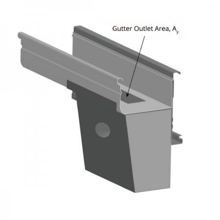
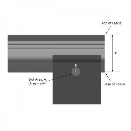
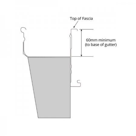
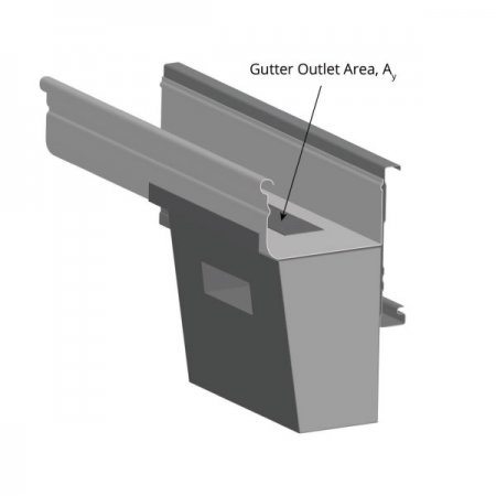
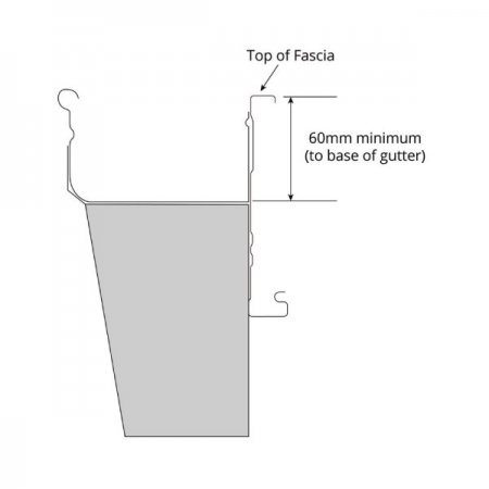
For a modern appeal, an aesthetically pleasing domestic rainhead can be selected to provide the full overflow allowance when designed appropriately. The overflow outlet in the rainhead shall be located at least 100mm from the top of the fascia with the base of the gutter at least 60mm from the top of the fascia.
Outlet/Slot Area, A
A = (Pi)R² (circular)
| Distance, X (mm) |
Minimum Gutter Outlet Area, Ay (mm²) |
Slot Area, Az (mm²) |
Overflow Capacity (L/s) |
| 100 | 4000 | greater than or equal to 3000 | 2.5 |
| 6000 | 4500 | 3.8 | |
| 8000 | 6000 | 5.1 | |
| 125 | 5000 | greater than or equal to 3000 | 2.8 |
| 7000 | 4500 | 4.2 | |
| 9000 | 6000 | 5.7 |
Note: For intermediate values of area, interpolation is permitted.
Outlet/Slot Area, A
A = BxD (rectangular)
| Distance, X (mm) |
Minimum Gutter Outlet Area, Ay (mm²) |
Slot Area, Az (mm²) |
Overflow Capacity (L/s) |
| 100 | 4000 | greater than or equal to 3000 | 2.5 |
| 6000 | 4500 | 3.8 | |
| 8000 | 6000 | 5.1 | |
| 125 | 5000 | greater than or equal to 3000 | 2.8 |
| 7000 | 4500 | 4.2 | |
| 9000 | 6000 | 5.7 |
Note: For intermediate values of area, interpolation is permitted.
Circular Overflow
Rectangular Overflow

Design Examples
Looking at a home located in Brisbane, QLD. Determine the overflow requirement for a 10m eaves gutter length with a
6m Ridge to Gutter Length.
Solution
Step 1
From Table 1 as noted earlier, the 5 minute duration rainfall intensity for an average recurrance interval of 100 years in Brisbane is 305mm/h. Round this value up to the closest 25mm/h increment, i.e. 325mm/h
Step 2
As we have the Ridge to Gutter Length of 5m, Table 2 is used to determine an interpolated value of 0.54L/s/m for a 325mm/h intensity. If required, the total overflow can be determined by multiplying this volume by the gutter length, i.e. 0.54 x 10m = 5.4L/s. Alternatively, if the Roof Catchment Area is known to be 60m², Table 3 is used to determine an interpolated overflow volume of 5.4L/s for a 325mm/h intensity.
Step 3
An approproate overflow solution can now be determined for this 10m run of gutter:
Option 1: Continuous Overflow Solution
Consider a 4.5mm Rear Exit Gap.
For this option the Overflow Capacity = 1.5L/s/m (refer page 5).
As 1.5 > 0.54L/s/m this is an acceptable solution.
Option 2: Dedicated Overflow Solution
Consider an internal outlet of dimensions 100mm x 50mm positioned lengthways in the gutter. The distance from the top of the fascia to the top of the outlet measures 30mm which is larger than the required minimum of 25mm. For this option the Overflow Capacity = 1.2L/s/m (refer page 6).
As 1.2 > 0.54L/s this is an acceptable solution.
Option 3: Combination Overflow Solution
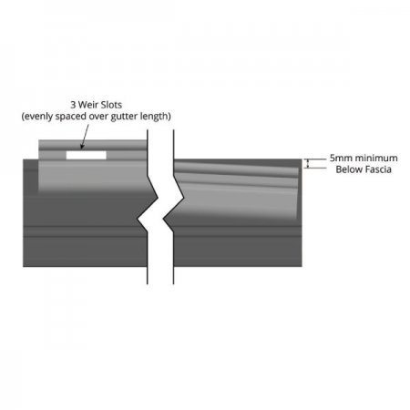
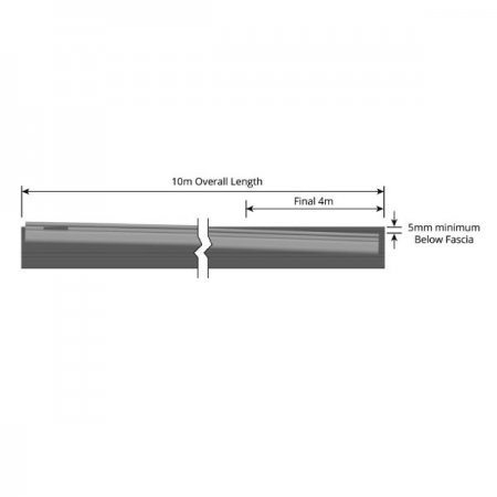
It is determined for the final 4m at the low end, the Front Gutter Height will be between 5mm and 10mm below the top of the fascia.
This will provide an Overflow Capacity = 0.6L/s/m (refer page 4) and therefore an overflow of 4m x 0.6 = 2.4L/s
Locate three equally spaced Front Face Weirs over the gutter length. Use 200mm width weirs which provide an Overflow Capacity = 1.0L/s each (refer page 6). This provides an overflow of 3 x 1.0 = 3.0L/s
The total overflow capacity for this combination: 2.4L/s + 3.0L/s = 5.4L/s which is equal to the required overflow volume so this is an acceptable solution.
Overflow Volumes
